Author Topic: Work in progress - large Technic project  (Read 14489 times)

0 Members and 1 Guest are viewing this topic.

Offline Tom a.k.a. eastawat

  • Lug.ie Team
  • Senior Member
  • ***
  • Posts: 659
  • Thanks: 6
  • County: Kildare
I've started building a large Technic vehicle and I'm going to document the building process here and share with you all how I go about planning and building something like this.

This began last year with the acquisition of the infra-red-controlled Technic bulldozer from 2007 (8275). I've had it in the back of my mind that I'd like to build a large motorised Technic vehicle for years, but never had the necessary motors, or any IR parts.

For inspiration on what to build, I went back to large-scale Technic trucks and construction vehicles I remember being in awe of in my early teens, circa 2001-2002. To set the scene, broadband hadn't reached Ireland yet, and in the online world of Lego, lugnet.com was still a big deal, brickshelf.com was THE site for hosting your creations, and most AFOLS who weren't on there had a Geocities page.

Around this time I discovered Technic models by Jennifer Clark (the most impressive at the time being her Hook Lift Truck. Her detailed write-up taught 13-ish-year-old me a very significant proportion of what I now know about Technic and how various mechanisms work, and very occasionally I refer back to that site to this day for reference.

So in honour of that great Technic creation, I've set upon building a MAN Hook Lift truck. For those of you not in the know, it's like a dump truck, except that on the back is essentially a big skip, which can be both "dumped" in the sense you'd expect, and rolled off the back of the truck altogether. I also plan to add a crane to it behind the cab, something like this, and where you have a crane you must have outriggers to prevent the vehicle from tipping over.

I plan to use four motors, plus pneumatics for the crane; each motor can perform more than one function, since not all functions will be required at any one time. Motorised functions will be:
  • Drive
  • Steering
  • Tipping
  • Extending outriggers
  • Lowering outriggers
  • Rotating the crane
  • Pneumatic compression
  • Switching each motor from one gear to another

Each motor will perform two functions. "How can the motor which switches functions also perform two functions itself!?" I hear you ask. With the first part of a mechanism that I posted recently! Both the function selector and the pneumatic compressor only need to turn one way, they have no need for a reverse, so I can use a mechanism which changes the output depending on direction.

I've set myself a few goals, number one being that I'm going to use the modern studless/brickless style of Technic building, which, when it comes to MOCs, I'm not at all accustomed to, but which is far more versatile than the old Technic brick style. Other goals include having a decent turning circle (most Technic sets have very poor steering lock due to the maximum angle a Lego ball socket and ball joint can turn in two out of three planes of motion), and making the model as modular as possible without compromising on strength and stability (this will rely a lot on pins with bushes connecting different modular sections). One concern was that I would have to give the model unrealistically large wheel-arches to accommodate the steering, but a test showed that a half-stud gap between the wheel and the inside of the arch was sufficient, as long as the interior of the wheel well was more roomy. You can see the wheel just clears the pink piece in this test:


To kick this project off I started with attempting to scale the model. I found this blueprint and from that I estimated the size when using these wheels, which are 62.4mm in diameter (about 7.75 studs):
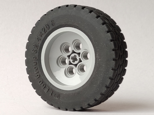

To cut a long story short, I got my measurements wrong (only realising a couple of days into building!), particularly with the width of the vehicle, which is better suited to 19 studs wide than 17 (it should be just over 18 studs wide but modern studless Technic works best in odd numbers). Here's the original 17-stud-wide plan:


I discovered when re-estimating the scale that famed Technic model-builder and blogger Sariel has an excellent scaling tool on his website, so armed with this knowledge I produced this, as well as a similar front-view version:


I had planned to incorporate a feature some of you may be familiar with, called Ackerman steering geometry. For the uninitiated, when you steer, your wheels trace the outlines of imaginary circles on the road. Your outside wheels trace a larger circle than your inside wheels, therefore the wheels should turn at different angles:


Ackerman geometry is achieved by attaching the steering rack at points on non-parallel lines - this Eurobricks topic shows how to correctly line up the pivot points. However, after a visual test I concluded that at my scale (and particularly due to the length of the vehicle), the wheels appeared to be so close to parallel that the impact of Ackerman geometry was negligible, so I decided not to bother with the added complication.

One of the main non-motorised features of the truck will be suspension, and in my first iteration of building the front axles I had each axle connected by four soft springs to the chassis, as well as one steering arm with towball socket. Here's one of the axles in its early stages:


It turned out that this was a bit unstable though and my wider second iteration uses three socket arms and two hard springs per axle. (Actually I currently have yellow 5L liftarms as placeholders for the socket arms, they're in the post from Bricklink...)
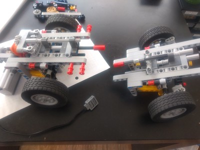

Fitting the motor to the front of the truck along with all the gearing required to switch functions and have two motor outputs (one for steering, one for crane rotation) was tricky, so I modeled the gears and axles without any supporting structure in stud.io first - this saved loads of hassle, since when you're designing gearing mechanisms, most of the time is actually taken up fiddling about with connectors and liftarms to get them into place, and then taking those apart over and over to modify the gearing until it works. This was surprisingly simple in the end:

The system is colour-coded in the stud.io model - red is directly powered by the motor, orange is the function selection axle, green drives the turntable and black drives the steering.

The next challenge is how to transmit steering power - initially I was linking a liftarm to the Technic axle which steers to each steering arm, but this seems to put a lot of strain on parts so I'm looking at using a rack and pinion with ball joints, but fitting that in and connecting the ball joints so that they're facing upwards instead of sideways (to avoid the problem of a poor turning circle) is proving challenging. And after building the front two axles of the truck twice now, with head-melting technical issues, I'm taking a break from Tehcnic for a couple of days.

Watch this space, further updates to follow!


Offline John

  • Lug.ie Team
  • Hero Member
  • ***
  • Posts: 2319
  • Thanks: 9
  • County: Limerick
Hope lockdown lasts long enough to see this completed, and the tutorials we all getting we'll be online mechanics(should everyone start driving technic vehicles)

Offline lisaloveslego

  • Lug.ie Team
  • Senior Member
  • ***
  • Posts: 330
  • Thanks: 6
  • County: Wexford
Thanks for sharing the details of your planning Tom!  As someone who doesn’t build Technic, I’m blown away by the amount of details that go into Technic builds.
Really looking forward to your updates!

Offline Tom a.k.a. eastawat

  • Lug.ie Team
  • Senior Member
  • ***
  • Posts: 659
  • Thanks: 6
  • County: Kildare
I've been tipping away at this but I've run into some issues. After two more iterations of building the front chassis (bringing the total to 5!) I couldn't find a satisfactory steering mechanism. All iterations of the chassis have the power from the motor passing through a function selector mechanism, one output of which drives an axle passing through the chassis to each steered axle. Each iteration uses one of two steering mechanisms:

1. Using an arm for each steered axle rotating off a single axle.

The black L-shaped liftarm connects the steering axle to what I guess you might call the tie rod which moves laterally to steer the wheels.

2. Using worm gears to turn small vertical 8-tooth gears on each set of wheels to rotate arms which connect to tie rods (Technic links with ball sockets).

Due to space restrictions, each steered axle has to have a separate worm gear - ideally they would be linked off a single gear but I couldn't find a way to join the two steering mechanisms.

Type 1 was unsatisfactory because there was a huge amount of slack in the system. The function selector allows for a lot of free rotation of the steering axle because Technic driving rings have about 90° of slack built into their design. It was almost impossible to steer to a certain angle, and it would take much too long for the motor to engage and turn the wheels. A possible solution was to use elastic bands to pull the steering to one side to eliminate the slack, but the power of elastic bands required to be effective felt like it was putting too much stress on the system.

Type 2, with worm gears located between the function selector mechanism and the steering, should have eliminated the slack. It did eliminate most of it, and fully eliminated the delay between the motor turning and engaging the steering, but due to each steered axle being connected via its own worm gear, the steered axles weren't always perfectly synchronised. Even with worm gears, one set of wheels could be aligned straight and the other set would still be turned 10° to one side.

My solution is a major redesign - it seems as though the steering can't be controlled with a motor that passes through a function selector. This means either sacrificing one of the functions or adding more functions to another motor elsewhere. I've opted for the latter. It'll make the function selection slightly more complicated and will make the controls a bit harder to use but seems worth it overall.

Now that the steering is going to be controlled by a single motor, I've decided to invest in a servo motor for finer control - it wouldn't have been possible to use a servo motor with multiple functions, but it is generally the preferred motor for Technic steering, particularly due to its ability to easily return to centre.

Offline Tom a.k.a. eastawat

  • Lug.ie Team
  • Senior Member
  • ***
  • Posts: 659
  • Thanks: 6
  • County: Kildare
An update on the progress on this... I've been designing the central workings in stud.io, trying to fit three of the motors and all the function selectors into a very tight space.


This (in theory - I would still need to build it to make sure it all works) is packed with functions:
One M motor leads to a directional selector - in one direction, in turns the sequential function selector for the other two motors; in the other direction, it runs a pneumatic compressor.
Depending on the sequential function selector, the second M motor will drive one of two outputs, and the XL motor will drive one of four outputs. The six green axle connectors are the outputs.

Unfortunately, although this is as compact as it would be possible to make all of this, it's too big for the space, and that's still with the outputs at chaotic locations. So I think I need to move at least two of the motors out of the centre of the truck and keep that area just for transmission, and maybe the function selector motor.

Offline Tom a.k.a. eastawat

  • Lug.ie Team
  • Senior Member
  • ***
  • Posts: 659
  • Thanks: 6
  • County: Kildare
A long-overdue update on this project! I decided to simplify the truck a lot - I no longer plan to add a crane or outriggers. I've designed a middle module for the truck with two motors and four functions.

Here's the module:

There's an XL motor on the left which provides the drive for the four functions, and an M motor on the right (quite hard to see) which powers the 90-degree stepper which switches between the functions.
The four functions will be:
1. Driveshaft (red) - this actually has an output at both ends of the module, as I'm now planning to make the truck all-wheel-drive.
2. Boom telescoping (yellow knob wheel) - hook-lift trucks can retract/extend their booms, to reduce the tipping angle when in skip-unloading mode (see this video).
3. Toggle between normal tipping and skip unloading (white)
4. Tipping (blue) - using linear actuators

I can't embed videos but I have a video on flickr demonstrating it in action:
https://flic.kr/p/2m9NgiW

Offline John

  • Lug.ie Team
  • Hero Member
  • ***
  • Posts: 2319
  • Thanks: 9
  • County: Limerick
A single steer and three on rear -tridrive or tridem. The crane body could be part of skip body. I've got a chain skip truck that can be motorised although you'd need to manually select the mode required. Highly ambitious but will be more than rewarding when complete!

Offline Tom a.k.a. eastawat

  • Lug.ie Team
  • Senior Member
  • ***
  • Posts: 659
  • Thanks: 6
  • County: Kildare
Double steering on 8x8! There will be a third (servo) motor for the steering, but it doesn't need to sit in the middle with the rest of the mechanism.

I've seen trucks where the crane is part of the skip, but I think unless the crane was completely manually operated the mechanisms would get too bulky and probably detract from the realism of the truck. I'll just save the crane option for a future project!

Here's an overview of the chassis as currently planned - this has a slightly older version of the central module, which I had to tweak quite a bit when I built it, but it gives an rough idea of the layout. I haven't figured out exactly how to connect up the front axles, at the moment they're just floating there. The steering isn't connected yet and I haven't settled on a final location for the servo motor.


Offline John

  • Lug.ie Team
  • Hero Member
  • ***
  • Posts: 2319
  • Thanks: 9
  • County: Limerick
I commend your making twin wheels on the rear axles but the most technic trucks stick with singles ,the skip truck I have has 3 axles all single but I turned one around to look deeper. I have some old technic pneumatic stuff I'll give you a look to see if anything catches your eye, maybe at weekend I'll photo the stuff

Offline Tom a.k.a. eastawat

  • Lug.ie Team
  • Senior Member
  • ***
  • Posts: 659
  • Thanks: 6
  • County: Kildare
Yeah it really bothers me that they have single wheels on the back axles... it was the only failing of 5571 and it's annoying that it's true of most Technic as well. 8285 had it right though!

You should hold onto your pneumatics, thanks for the offer though. I have more than I know what to do with, just won't be able to fit it into this MOC!

Offline Tom a.k.a. eastawat

  • Lug.ie Team
  • Senior Member
  • ***
  • Posts: 659
  • Thanks: 6
  • County: Kildare


I've built two front axles that I'm very pleased with. The front of the vehicle is the end at the left side of the photo. It's not yet connected to a chassis, but I'll hopefully get that done tomorrow. The axles are driven and steered, with the drive shaft connecting to the universal joint on the very right of the photo, and the steering controlled by the shaft at the top with the yellow connectors on it.

A difference in steering angle between the first and second axles is achieved with the different lengths of the connections from the steering shaft to the tie rods. The distance is two studs on the front axle and 1.5 studs on the second axle thanks to the extra axle hole in this piece, meaning that when the steering shaft turns, the tie rods are pulled different distances.

This features "live axle" (or solid axle) suspension, as a truck of this sort should have* - in other words each of the two big parts of this will be suspended entirely, as opposed to individual wheels being suspended - here's an image for comparison. They'll connect to the chassis by the two black ball joints on top of each axle, and by the springs... hopefully this will be a solid enough connection and they won't flex around the place!

*However I'm using coil springs as opposed to leaf springs which a truck like this should have; although leaf springs can sort of be done with Lego, they rely on bending axles, which I don't want to subject my pieces to!

Offline John

  • Lug.ie Team
  • Hero Member
  • ***
  • Posts: 2319
  • Thanks: 9
  • County: Limerick
This level of detail in the build process must be extra workload but also enjoyable and maybe an enhancement to the build ,thanks Tom


lego